Centrifugal pump principles and working procedure
A pump is a machine used to raise liquids from a low point to a high point. In a centrifugal pump liquid enters the centre or eye of the impeller and flows radially out between the vanes, its velocity being increased by the impeller rotation. A diffuser or volute is then used to convert most of the kinetic energy in the liquid into pressure.
The arrangement of a centrifugal pump is shown diagrammatically in figure below
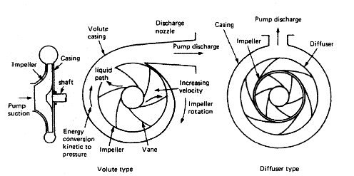
Fig: Centrifugal pumping operation
A vertical, single stage, single entry, centrifugal pump for general marine duties is shown in Figure here. The main frame and casing, together with a motor support bracket, house the pumping element assembly. The pumping element is made up of a top cover, a pump shaft, an impeller, a bearing bush and a sealing arrangement around the shaft. The sealing arrangement may be a packed gland or a mechanical seal and the bearing lubrication system will vary according to the type of seal. Replaceable wear rings are fitted to the impeller and the casing. The motor support bracket has two large apertures to provide access to the pumping element, and a coupling spacer is fitted between the motor and pump shaft to enable the removal of the pumping element without disturbing the motor.
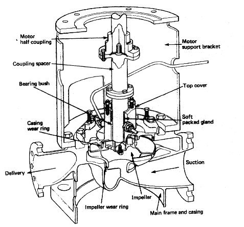
Fig: Single entry centrifugal pump
A vertical multi-stage single-entry centrifugal pump used for deep-well cargo pumping is shown in Figure below. This can be considered as a series of centrifugal pumps arranged to supply one another in series and thus progressively increase the discharge pressure. The pump drive is located outside the tank and can be electric, hydraulic or any appropriate means suitable for the location.
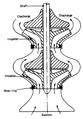
Fig: Multi stage centrifugal pump
A diffuser is fitted to high-pressure centrifugal pumps. This is a ring fixed to the casing, around the impeller, in which there are passages formed by vanes. The passages widen out in the direction of liquid flow and act to convert the kinetic energy of the liquid into pressure energy. Hydraulic balance arrangements are also usual. Some of the high-pressure discharge liquid is directed against a drum or piston arrangement to balance the discharge liquid pressure on the impeller and thus maintain it in an equilibrium position.
Centrifugal pumps, while being suitable for most general marine duties, are not self priming and require some means of removing air from the suction pipeline and filling it with liquid. Where the liquid to be pumped is at a level higher than the pump, opening an air cock near the pump suction will enable the air to be forced out as the pipeline fills up under the action of gravity. If the pump is below sea water level, and sea water priming is permissible in the system, then opening a sea water injection valve and the air cock on the pump will effect priming.
Alternatively an air pumping unit can be provided to individual pumps or as a central priming system connected to several pumps. The water ring or liquid ring primer can be arranged as an individual unit mounted on the pump and driven by it, or as a motor driven unit mounted separately and serving several pumps. The primer consists of an elliptical casing in which a vaned rotor revolves. The rotor may be separate from the hub and provide the air inlet and discharge ports as shown in Figure down. Alternatively another design has the rotor and hub as one piece with ports on the cover. The rotor vanes revolve and force a ring of liquid to take up the elliptical shape of the casing. The water ring, being elliptical, advances and recedes from the central hub, causing a pumping action to occur. The suction piping system is connected to the air inlet ports and the suction line is thus primed by the removal of air. The air removed from the system is discharged to atmosphere. A reservoir of water is provided to replenish the water ring when necessary.
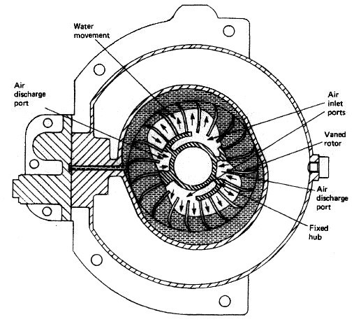
Fig: Water-ring primer
When starting a centrifugal pump the suction valve is opened and the discharge valve left shut: then the motor is started and the priming unit will prime the suction line. Once the pump is primed the delivery valve can be slowly opened and the quantity of liquid can be regulated by opening or closing the delivery valve. When stopping the pump the delivery valve is closed and the motor stopped.
Regular maintenance on the machine will involve attention to lubrication of the shaft bearing and ensuring that the shaft seal or gland is not leaking liquid. Unsatisfactory operation or loss of performance may require minor or major overhauls. Common faults, such as no discharge, may be a result of valves in the system being shut, suction strainers blocked or other faults occurring in the priming system. Air leaks in the suction piping, a choked impeller or too tight a shaft gland can all lead to poor performance.
When dismantling the pump to remove the pumping element any priming pipes or cooling water supply pipes must be disconnected. Modern pumps have a coupling spacer which can be removed to enable the pumping element to be withdrawn without disturbing the motor: the impeller and shaft can then be readily separated for examination. The shaft bearing bush together with the casing and impeller wear rings should be examined for wear.
Section B -- Pump Application Data B-4A Sealing
The proper selection of a seal is critical to the success of every pump application. For maximum pump reliability, choices must be made between the type of seal and the seal environment. In addition, a sealless pump is an alternative, which would eliminate the need for a dynamic type seal entirely.
Sealing Basics
There are two basic kinds of seals: static and dynamic. Static seals are employed where no movement occurs at the Juncture to be sealed. Gaskets and O-rings are typical static seals.
Dynamic seals are used where surfaces move relative to one another. Dynamic seals are used, for example, where a rotating shaft transmits power through the wall of a tank (Fig. 1), through the casing of a pump (Fig. 2), or through the housing of other rotating equipment such as a filter or screen.

Fig. 1 Cross Section of Tank and Mixer

Fig. 2 Typical Centrifugal Pump A common application of sealing devices is to seal the rotating shaft of a centrifugal pump. To best understand how such a seal functions a quick review of pump fundamentals is in order.
In a centrifugal pump, the liquid enters the suction of the pump at the center (eye) of the rotating impeller (Figures 3 and 4).

Fig. 3 Centrifugal Pump, Liguid End

Fig. 4 Fluid Flow in Centrifugal Pump As the impeller vanes rotate, they transmit motion to the incoming product, which then leaves the impeller, collects in the pump casing, and leaves the pump under pressure through the pump discharge.
Discharge pressure will force some product down behind the impeller to the drive shaft, where it attempts to escape along the rotating drive shaft. Pump manufacturers use various design techniques to reduce the pressure of the product trying to escape. Such techniques include: 1) the addition of balance holes through the impeller to permit most of the pressure to escape into the suction side of the impeller, or 2) the addition of back pump-out vanes on the back side of the impeller.
However, as there is no way to eliminate this pressure completely, sealing devices are necessary to limit the escape of the product to the atmosphere. Such sealing devices are typically either compression packing or end-face mechanical seals.
B-4A Stuffing Box Packing
A typical packed stuffing box arrangement is shown in Fig. 5. It consists of: A) Five rings of packing, B) A lantern ring used for the injection of a lubricating and/or flushing liquid, and C) A gland to hold the packing and maintain the desired compression for a proper seal.

Fig. 5 Typical Stuffing Arrangement (description of parts) The function of packing is to control leakage and not to eliminate it completely. The packing must be lubricated, and a flow from 40 to 60 drops per minute out of the stuffing box must be maintained for proper lubrication.
The method of lubricating the packing depends on the nature of the liquid being pumped as well as on the pressure in the stuffing box. When the pump stuffing box pressure is above atmospheric pressure and the liquid is clean and nonabrasive, the pumped liquid itself will lubricate the packing (Fig. 6).

Fig. 6 Typical Stuffing Arrangement when Stuffing Box Pressure is Above Atmospheric Pressure When the stuffing box pressure is below atmospheric pressure, a lantern ring is employed and lubrication is injected into the stuffing box (Fig. 7). A bypass line from the pump discharge to the lantern ring connection is normally used providing the pumped liquid is dean.

Fig. 7 Typical Stuffing Box Arrangement when Stuffing Box Pressure is Below Atmospheric Pressure When pumping slurries or abrasive liquids, it is necessary to inject a dean lubricating liquid from an external source into the lantern ring (Fig. 8). A flow of from .2 to .5 gpm is desirable and a valve and flowmeter should be used for accurate control. The seal water pressure should be from 10 to 15 psi above the stuffing box pressure, and anything above this will only add to packing wear. The lantern ring Is normally located In the center of the stuffing box. However, for extremely thick slurries like paper stock, it is recommended that the lantern ring be located at the stuffing box throat to prevent stock from contaminating the packing.

Fig. 8 Typical Stuffing Box Arrangement when Pumping Slurries The gland shown in Figures 5 through 8 is a quench type gland. Water, oil, or other fluids can be injected into the gland to remove heat from the shaft, thus limiting heat transfer to the bearing frame. This permits the operating temperature of the pump to be higher than the limits of the bearing and lubricant design. The same quench gland can be used to prevent the escape of a toxic or volatile liquid into the air around the pump. This is called a smothering gland, with an external liquid simply flushing away the undesirable leakage to a sewer or waste receiver.
Today, however, stringent emission standards limit use of packing to non-hazardous water based liquids. This, plus a desire to reduce maintenance costs, has increased preference for mechanical seals.
Mechanical Seals
A mechanical seal is a sealing device which forms a running seal between rotating and stationary parts. They were developed to overcome the disadvantages of compression packing. Leakage can be reduced to a level meeting environmental standards of government regulating agencies and maintenance costs can be lower. Advantages of mechanical seals over conventional packing are as follows:
- Zero or limited leakage of product (meet emission regulations.)
- Reduced friction and power loss.
- Elimination of shaft or sleeve wear.
- Reduced maintenance costs.
- Ability to seal higher pressures and more corrosive environments.
- The wide variety of designs allows use of mechanical seals in almost all pump applications.
The Basic Mechanical Seal
All mechanical seals are constructed of three basic sets of parts as shown in Fig. 9:
- A set of primary seal faces: one rotary and one stationary?shown in Fig. 9 as seal ring and insert.
- A set of secondary seals known as shaft packings and insert mountings such as 0-rings, wedges and V-rings.
- Mechanical seal hardware including gland rings, collars, compression rings, pins, springs and bellows.

Fig. 9 A Simple Mechcanical Seal How A Mechanical Seal Works
The primary seal is achieved by two very flat, lapped faces which create a difficult leakage path perpendicular to the shaft. Rubbing contact between these two flat mating surfaces minimizes leakage. As in all seals, one face is held stationary in a housing and the other face is fixed to, and rotates with, the shaft. One of the faces is usually a non-galling material such as carbon-graphite. The other is usually a relatively hard material like silicon-carbide. Dissimilar materials are usually used for the stationary insert and the rotating seal ring face in order to prevent adhesion of the two faces. The softer face usually has the smaller mating surface and is commonly called the wear nose.
There are four main sealing points within an end face mechanical seal (Fig. 10). The primary seal is at the seal face, Point A. The leakage path at Point B is blocked by either an 0-ring, a V-ring or a wedge. Leakage paths at Points C and D are blocked by gaskets or 0-rings.

Fig. 10 Sealing Points for Mechanical Seal The faces in a typical mechanical seal are lubricated with a boundary layer of gas or liquid between the faces. In designing seals for the desired leakage, seal life, and energy consumption, the designer must consider how the faces are to be lubricated and select from a number of modes of seal face lubrication.
To select the best seal design, it's necessary to know as much as possible about the operating conditions and the product to be sealed. Complete information about the product and environment will allow selection of the best seal for the application.
Mechanical Seal Types
Mechanical seals can be classified into several tvpes and arrangements:

PUSHER:
Incorporate secondary seals that move axially along a shaft or sleeve to maintain contact at the seal faces. This feature compensates for seal face wear and wobble due to misalignment. The pusher seals' advantage is that it's inexpensive and commercially available in a wide range of sizes and configurations. Its disadvantage is that ft's prone to secondary seal hang-up and fretting of the shaft or sleeve. Examples are Dura RO and Crane Type 9T.

UNBALANCED:
They are inexpensive, leak less, and are more stable when subjected to vibration, misalignment, and cavitation. The disadvantage is their relative low pressure limit. If the closing force exerted on the seal faces exceeds the pressure limit, the lubricating film between the faces is squeezed out and the highly loaded dry running seal fails. Examples are the Dura RO and Crane 9T.

CONVENTIONAL:
Examples are the Dura RO and Crane Type 1 which require setting and alignment of the seal (single, double, tandem) on the shaft or sleeve of the pump. Although setting a mechanical seal is relatively simple, today's emphasis on reducing maintenance costs has increased preference for cartridge seals.

NON-PUSHER:
The non-pusher or bellows seal does not have to move along the shaft or sleeve to maintain seal face contact, The main advantages are its ability to handle high and low temperature applications, and does not require a secondary seal (not prone to secondary seal hang-up). A disadvantage of this style seal is that its thin bellows cross sections must be upgraded for use in corrosive environments Examples are Dura CBR and Crane 215, and Sealol 680.

BALANCED:
Balancing a mechanical seal involves a simple design change, which reduces the hydraulic forces acting to close the seal faces. Balanced seals have higher-pressure limits, lower seal face loading, and generate less heat. This makes them well suited to handle liquids with poor lubricity and high vapor pressures such as light hydrocarbons. Examples are Dura CBR and PBR and Crane 98T and 215.

CARTRIDGE:
Examples are Dura P-SO and Crane 1100 which have the mechanical seal premounted on a sleeve including the gland and fit directly over the Model 3196 shaft or shaft sleeve (available single, double, tandem). The major benefit, of course is no requirement for the usual seal setting measurements for their installation. Cartridge seals lower maintenance costs and reduce seal setting errors
Mechanical Seal Arrangements
SINGLE INSIDE:
This is the most common type of mechanical seal. These seals are easily modified to accommodate seal flush plans and can be balanced to withstand high seal environment pressures. Recommended for relatively clear non-corrosive and corrosive liquids with satisfactory' lubricating properties where cost of operation does not exceed that of a double seal. Examples are Dura RO and CBR and Crane 9T and 215. Reference Conventional Seal.
SINGLE OUTSIDE:
If an extremely corrosive liquid has good lubricating properties, an outside seal offers an economical alternative to the expensive metal required for an inside seal to resist corrosion. The disadvantage is that it is exposed outside of the pump which makes it vulnerable to damage from impact and hydraulic pressure works to open the seal faces so they have low pressure limits (balanced or unbalanced).

DOUBLE (DUAL PRESSURIZED):
This arrangement is recommended for liquids that are not compatible with a single mechanical seal (i.e. liquids that are toxic, hazardous [regulated by the EPA], have suspended abrasives, or corrosives which require costly materials). The advantages of the double seal are that it can have five times the life of a single seal in severe environments. Also, the metal inner seal parts are never exposed to the liquid product being pumped, so viscous, abrasive, or thermosetting liquids are easily sealed without a need for expensive metallurgy. In addition, recent testing has shown that double seal life is virtually unaffected by process upset conditions during pump operation. A significant advantage of using a double seal over a single seal. The final decision between choosing a double or single seal comes down to the initial cost to purchase the seal, cost of operation of the seal, and environmental and user plant emission standards for leakage from seals. Examples are Dura double RO and X-200 and Crane double 811T.

DOUBLE GAS BARRIER (PRESSURIZED DUAL GAS):
Very similar to cartridge double seals ... sealing involves an inert gas, like nitrogen, to act as a surface lubricant and coolant in place of a liquid barrier system or external flush required with conventional or cartridge double seals. This concept was developed because many barrier fluids commonly used with double seals can no longer be used due to new emission regulations. The gas barrier seal uses nitrogen or air as a harmless and inexpensive barrier fluid that helps prevent product emissions to the atmosphere and fully complies with emission regulations. The double gas barrier seal should be considered for use on toxic or hazardous liquids that are regulated or in situations where increased reliability is the required on an application. Examples are Dura GB2OO, GF2OO, and Crane 2800.

TANDEM (DUAL UNPRESSURIZED): Due to health, safety, and environmental considerations, tandem seals have been used for products such as vinyl chloride, carbon monoxide, light hydrocarbons, and a wide range of other volatile, toxic, carcinogenic, or hazardous liquids.
Tandem seals eliminate icing and freezing of light hydrocarbons and other liquids which could fall below the atmospheric freezing point of water in air (32? F or 0? C). {Typical buffer liquids in these applications are ethylene glycol, methanol, and propanol.) A tandem also increases online reliability. If the primary seal fails, the outboard seal can take over and function until maintenance of the equipment can be scheduled. Examples are Dura TMB-73 and tandem PTO.
Mechanical Seal Selection
The proper selection of a mechanical seal can be made only if the full operating conditions are known:
- Liquid
- Pressure
- Temperature
- Characteristics of Liquid
- Reliability and Emission Concerns
- Liquid: Identification of the exact liquid to be handled is the first step in seal selection. The metal parts must be corrosion resistant, usually steel, bronze, stainless steel, or Hastelloy. The mating faces must also resist corrosion and wear. Carbon, ceramic, silicon carbide or tungsten carbide may be considered. Stationary sealing members of Buna, EPR, Viton and Teflon are common.
- Pressure: The proper type of seal, balanced or unbalanced, is based on the pressure on the seal and on the seal size.
- Temperature: In part, determines the use of the sealing members. Materials must be selected to handle liquid temperature.
- Characteristics of Liquid: Abrasive liquids create excessive wear and short seal life. Double seals or clear liquid flushing from an external source allow the use of mechanical seals on these difficult liquids. On light hydrocarbons balanced seals are often used for longer seal life even though pressures are low.
- Reliability and Emission Concerns: The seal type and arrangement selected must meet the desired reliability and emission standards for the pump application. Double seals and double gas barrier seals are becoming the seals of choice.
Seal Environment
The number one cause of pump downtime is failure of the shaft seal. These failures are normally the result of an unfavorable seal environment such as improper heat dissipation (cooling), poor lubrication of seal faces, or seals operating in liquids containing solids, air or vapors. To achieve maximum reliability of a seal application, proper choices of seal housings (standard bore stuffing box, large bore, or large tapered bore seal chamber) and seal environmental controls (CPI and API seal flush plans) must be made. STANDARD BORE STUFFING BOX COVER
Designed thirty years ago specifically for packing. Also accommodates mechanical seals (clamped seat outside seals and conventional double seals.)

CONVENTIONAL LARGE BORE SEAL CHAMBER
Designed specifically for mechanical seals. Large bore provides Increased life of seals through improved lubrication and cooling of faces. Seal environment should be controlled through use of CPI or API flush plans. Often available with internal bypass to provide circulation of liquid to faces without using external flush. Ideal for conventional or cartridge single mechanical seals in conjunction with a flush and throat bushing in bottom of chamber. Also excellent for conventional or cartridge double or tandem seals.
 LARGE BORE SEAL CHAMBERS
Introduced in the mid-8o's, enlarged bore seal chambers with increased radial clearance between the mechanical seal and seal chamber wall, provide better circulation of liquid to and from seal faces. Improved lubrication and heat removal (cooling) of seal faces extend seal life and lower maintenance costs.
 BigBoreTM Seal Chamber
 TaperBoreTM Seal Chamber
Large Tapered Bore Seal Chambers
Provide increased circulation of liquid at seal faces without use of external flush. Offers advantages of lower maintenance costs, elimination of tubing/piping, lower utility costs (associated with seal flushing) and extended seal reliability. The tapered bore seal chamber is commonly available with ANSI chemical pumps. API process pumps use conventional large bore seal chambers. Paper stock pumps use both conventional large bore and large tapered bore seal chambers. Only tapered bore seal chambers with flow modifiers provide expected reliability on services with or without solids, air or vapors.
Conventional Tapered Bore Seal Chamber:
Mechanical Seals Fall When Solids or Vapors Am Present in Liquid
Many users have applied the conventional tapered bore seal chamber to improve seal life on services containing solids or vapors. Seals in this environment failed prematurely due to entrapped solids and vapors. Severe erosion of seal and pump parts, damaged seal faces and dry running were the result.
 Modified Tapered Bore Seal Chamber with Axial Ribs:
Good for Services Containing Air, Minimum Solids
This type of seal chamber will provide better seal life when air or vapors are present in the liquid. The axial ribs prevent entrapment of vapors through.improved flow in the chamber. Dry running failures are eliminated. In addition, solids less than 1% are not a problem.
The new flow pattern, however, still places the seal in the path of solids/liquid flow. The consequence on services with significant solids (greater than 1%) is solids packing the seal spring or bellows, solids impingement on seal faces and ultimate seal failure.
 Goulds Standard TaperBoreTM PLUS Seal Chamber: The Best Solution for Services Containing Solids and Air or Vapors
To eliminate seal failures on services containing vapors as well as solids, the flow pattern must direct solids away from the mechanical seal, and purge air and vapors. Goulds Standard TaperBoreTM PLUS completely reconfigures the flow in the seal chamber with the result that seal failures due to solids are eliminated. Air and vapors are efficiently removed eliminating dry run failures. Extended seal and pump life with lower maintenance costs are the results.
Goulds TaperBoreTM Plus: How It Works
The unique flow path created by the Vane Particle Elector directs solids away from the mechanical seal, not at the seal as with other tapered bore designs. And the amount of solids entering the bore is minimized. Air and vapors are also efficiently removed. On services with or without solids, air or vapors, Goulds TaperBoreTM PLUS is the effective solution for extended seal and pump life and lower maintenance costs. - Solids/liquid mixture flows toward mechanical seal/seal chamber.
- Turbulent zone. Some solids continue to flow toward shaft. Other solids are forced back out by centrifugal force (generated by back pump-out vanes).
- Clean liquid continues to move toward mechanical seal faces. Solids, air, vapors flow away from seal.
- Low pressure zone create by Vane Particle Ejector. Solids, air, vapor liquid mixture exit seal chamber bore.
- Flow in TaperBoreTMPLUS seal chamber assures efficient heat removal (cooling) and lubrication. Seal face heat is dissipated. Seal faces are continuously flushed with clean liquid.
 Stuffing Box Cover and Seal Chamber Guide
The selection guide on this page and the Seal Chamber Guide are designed to assist selection of the proper seal housing for a pump application.

JACKETED STUFFING BOX COVER
Designed to maintain proper temperature control (heating or cooling) of seal environment. (Jacketed covers do not help lower seal face temperatures to any significant degree). Good for high temperature services that require use of a conventional double seal or single seal with a flush and API or CPI plan 21. 
JACKETED LARGE BORE SEAL CHAMBER
Maintains proper temperature control (heating or cooling) of sea environment with improved lubrication of seal faces. Ideal for controlling temperature for services such as molten sulfur and polymerizing liquids. Excellent for high temperature services that require use of conventional or cartridge single mechanical seals with flush and throat bushing in bottom of seal chamber. Also, great for conventional or cartridge double or tandem seals.
Stuffing Box and Seal Chamber Application Guide
| Stuffing Box Cover/Seal Chamber | Application |
| Standard Bore Stuffing Box Cover | Use for soft packing. Outside mechanical seals. Double seals. Also, accommodates other mechanical seals. |
| Jacketed Stuffing Box Cover | Same as above but also need to control temperatures of liquid in seal area. |
| Conventional Large Bore | Use for all mechanical seal applications where the seal environment requires use of CPI or API seal flush pans. Cannot be used with outside type mechanical seals. |
| Jacketed Large Bore | Same as Large Bore but also need to control temperature of liquid in seal area. |
| Tapered Large Bore with Axial Ribs | Clean services that require use of single mechanical seals. Can also be used with cartridge double seals. Also, effective on services with light solids up to 1% by weight. Paper stock to 1% by weight. |
| Tapered Large Bore with Patented Vane Particle Ejector (Alloy Construction) | Services with light to moderate solids up to 10% by weight. Paper stock to 5% by weight. Ideal for single mechanical seals. No flush required. Also, accommodates double seals. Cannot be used with outside mechanical seals. |
Environmental Controls
Environmental controls are necessary for reliable performance of a mechanical seal on many applications. Goulds Pumps and the seal vendors offer a variety of arrangements to combat these problems.
1. Corrosion
2. Temperature Control
3. Dirty or incompatible environments
CORROSION
Corrosion can be controlled by selecting seal materials that are not attacked by the pumpage. When this is difficult, external fluid injection of a non-corrosive chemical to lubricate the seal is possible. Single or double seals could be used, depending on if the customer can stand delusion of his product. TEMPERATURE CONTROL
As the seal rotates, the faces are in contact. This generates heat and if this heat is not removed, the temperature in the stuffing box or seal chamber can increase and cause sealing problems. A simple by-pass of product over the seal faces will remove the heat generated by the seal (Fig. 25). For higher temperature services, by-pass of product through a cooler may be required to cool the seal sufficiently (Fig. 26). External cooling fluid injection can also be used.
 DIRTY or INCOMPATIBLE ENVIRONMENTS
Mechanical seals do not normally function well on liquids which contain solids or can solidify on contact with the atmosphere. Here, by-pass flush through a filter, a cyclone separator or a strainer are methods of providing a clean fluid to lubricate seal faces. Strainers are effective for particles larger than the openings on a 40 mesh screen. Cyclone separators are effective on solids 10 micron or more in diameter, if they have a specific gravity of 2.7 and the pump develops a differential pressure of 30-40 psi. Filters are available to remove solids 2 microns and larger.
If external flush with clean liquid is available, this is the most fail proof system. Lip seal or restricting bushings are available to control flow of injected fluid to flows as low as 1/8 GPM. Quench type glands are used on fluids which tend to crystallize on exposure to air. Water or steam is put through this gland to wash away any build up. Other systems are available as required by the service.


 BigBoreTM Seal Chamber
 TaperBoreTM Seal Chamber


