Saturday 29 October 2011

The Charge Air Cooler in Diesel Engines


The charge air cooler is an important device fitted in all turbocharged diesel engines to reduce the temperature of the charged air before its entry to the engine in order to increase the efficiency of engine. This article deals with purpose, location, and maintenance of charge air coolers.
In this article we discuss the charge air cooler fitted between the turbocharger and the scavenge air manifold in all modern four stroke and two stroke engines. Readers will be able to understand the concept of charge air coolers, and their operation, construction, and maintenance. One can also find reasons for cooler fouling, its location on engine, and methods of cleaning the charge air cooler.

Purpose of Charge Air Cooler

The exhaust gas from the engine is utilized in the turbocharger for compressing fresh air to charge the engine with a positive pressure greater than ambient conditions. This compression causes the temperature of the air to increase, which thus cannot be fed directly into the engine as it is out of operating limits. Thus a cooler that bring the air temperature back to near-ambient conditions is fitted on the engine. When the air is hot, its density is less and thus the mass of air charged into the engine is less when compared to the mass when the air is cold. Thus the charge air cooler improves the charge air density and its temperature.

The compressed charged air at the outlet of charge air cooler will have a reduced temperature of about 40 to 50 degrees Celsius from a temperature of about 200 degrees Celsius. This reduced temperature of air will increase the density of the charge air at low temperature. Increased air density of the charge air will rise the scavenge efficiency and allow a greater mass of air to be compressed inside the engine cylinder so that more fuel can be burned inside the combustion chamber, giving an increase in power. Also the engine is maintained at a safe working temperature. The lower compression temperature reduces stress on the piston, piston rings, cylinder liner, and cylinder head. The charge air cooler has another advantage in that it reduces the exhaust gas temperature. It has been proven that every one degree Celsius drop in scavenge air temperature will reduce the exhaust temperature about five to ten degree Celsius. This does not mean that the air can be charged at cryogenic temperatures. If very cold air enters the cylinder liner, it would cause a sudden thermal shock, leading to cracking of liner.
Thus charge air coolers also serve as heaters when a ship enters cold climate areas. Let us assume that the charge air cooler is cooled by fresh water (LT) circuit. If the ambient air temperature is very low, the fresh water, which is usually at 30 degrees Celsius, will heat the charged air and make it comfortable for the engine.

Charge Air Cooler

Charg Air Cooler External ViewHow Charge Air Cooler WorksCharge Air CoolerCharge Air CoolerCharge Air Cooler

Location of a Charge Air Cooler

Charge air coolers are located between the turbocharger compressor side outlet and the engine inlet manifold or scavenge manifold. A clear view of the location of a charge air cooler is shown in the diagram below. The location of the charge air cooler between turbocharger and entry to engine should be such that the temperature of the charge air at the outlet of charge air cooler should not be increased before its entry to the engine cylinder due to the heated condition of the engine room. To avoid this, the air cooler should be located as close to the engine cylinder as possible. Also, the air duct between the charge air cooler and the engine inlet manifold should be insulated to avoid increase in the temperature of the air.

Location of Cooler on Large Diesel Engine

Location of Cooler on Large Diesel EngineLocation of Cooler on Large Diesel Engine

Air Cooler Fouling and its Effect on the Engine

When the air cooler becomes fouled, less heat will be transferred from the air to the cooling water (usually fresh water). This is indicated by the changes in the air temperature and cooling water temperature and a pressure drop in the air passing through the air cooler. To measure this pressure drop, a manometer is connected between the charge air cooler inlet and outlet. The amount of pressure drop will depend upon the degree and nature of the fouling.
Indications of Air Side Fouling:
  • Increase of air pressure drop across the charge air cooler.
  • Decrease of air temperature difference across air cooler.
  • Rise in scavenge air temperature.
  • Rise in exhaust gas temperature from all cylinders.
Indications of cooling water side fouling:
  • Rise in scavenge air temperature.
  • Decrease in the difference of the air temperature across the air cooler.
  • Decrease in the temperature of the cooling water across the cooler if fouling is on the tubes.
  • Increase in exhaust gas temperature from all cylinders.
  • Increase in the temperature of the cooling water due to fouling or chocking material in tubes that reduce the amount of cooling water flow.
Methods of air side cleaning:
  • Fins in the air side can be cleaned by using compressed air at Low pressure.
  • The air side can be cleaned by dipping the air cooler in a chemical bath for a certain period of time. This will remove all deposits on the air side.
  • Another method of cleaning the air side is by using the jet of water at Low pressure.
  • Note: Usage of very high pressure may lead to bending of fins and thus causing permanent damage to the air cooler.
Methods of Fresh water side cleaning:
  • For soft deposits on the water side, dip the cooler in a chemical bath. After a certain period of time, take the cooler out and then clean with water at some temperature higher than ambient. It is always preferred to circulate water using wilden pump and drums.
  • For hard deposits use a long drill bit to drill the hard deposits on the tubes. Note this requires a specialist to drill the hard deposits because small mistakes in drilling may damage the tubes.

Sunday 16 October 2011

Centrifugal Oil Purifiers - Starting and Stopping Procedures


We have already discussed the basic principle of operation of purifiers. Lets learn how to start and stop purifiers, and about necessary safety precautions before starting, de-sludging procedures, and emergency stopping.
We all know that centrifuges are an important type of auxiliary equipment on board ships and that they are classified into two operating functions. One is a clarifier, which separates solids from liquids. The other type is a purifier, which separates liquids of different density. The Purifier operates on the principle of separation by centrifugal force. But in order to optimize the purification process, certain parameters should be adjusted before the purifier is started. Out of those parameters, very important parameters are:
  1. Feed inlet oil temperature
  2. Density of Oil
  3. RPM of the rotating bowl
  4. Back Pressure
  5. Throughput of oil feed

Understanding the Parameters

1. Feed inlet oil temperature: Before entering the purifier, the dirty oil passes through the heater. This increases the temperature, thus reducing the viscosity of the oil to be purified. The lower the viscosity, the better will be the purification.
2. Density of Oil: As the dirty oil entering the purifier is heated to reduce the viscosity, the density also reduces. The lower the density, the better the separation.
The digital factory Wastewater recycling.
3. R.P.M of the rotating bowl: If the purifier has not achieved full RPM (revolutions per second), then the centrifugal force will not be sufficient enough to aid the separation.
4. Back Pressure: The back pressure should be adjusted after the purifier is started. The back pressure varies as the temperature, density, viscosity of feed oil inlet varies. The back pressure ensures that the oil paring disc is immersed in the clean oil on the way of pumping to the clean oil tank.
5. Throughput of oil feed: Throughput means the quantity of oil pumped into the purifier/hr. In order to optimize the purification, the throughput must be minimum.

Pre-checks before starting a Purifier

Before starting a Purifier, following checks are very essential:
1. If the Purifier is started after a overhaul, then check all fittings are fiited in right manner. The bowl frame hood locked with hinges.
2. Check the Oil level in the gear case. Ensure that it is exactly half in the sight glass. Also ensure the sight glass is in vertical position, as there is a common mistake of fixing it in horizontal position.
3. check the direction of rotation of the seperator, by just starting and stopping the purifier motor.
4. Check whether the brake is in released position.

Starting the Purifier

1. Ensure the lines are set and respective valves are open. Usually the lines are set from settling tank to service tank.
2. Start the purifier feed pump with the 3-way re-circulation valve in a position leading to settling tank.
3. Open the steam to the heater slightly ensuring the drains are open so that the condensate drains. close the drains once steam appears.
4. Start the Purifier.
5. Check for vibrations, check the gear case for noise and abnormal heating.
6. Note the current (amps) during starting. It goes high during starting and then when the purifier bowl picks-up speed and when it reaches the rated speed, the current drawn drops to normal value.
7. Ensure the feed inlet temperature has reached optimum temperature for separation as stated in the Bunker report and nomogram ( bunker delivery note gives the density of the fuel and using this we can get the separation temperature and gravity disc size from the nomogram)
8. Now check whether the bowl has reached the rated speed by looking at the revolution counter. The revolution counter gives the scaled down speed of the bowl. The ratio for calculation can be obtained from the manual.
9. Now, after the bowl reaching the rated RPM, check for the current attaining its normal value.

De-sludge Procedure


10. Open the bowl closing water/operating water, which closes the bowl. (Ensure sufficient water is present in the operating water tank)
11. Now after 10 seconds, open the sealing water to the bowl.
12. The sealing water should be kept open till the water comes out of the waste water outlet.
13. Once the water overflows through the waste water outlet, stop the sealing water.
14. Now open the de-sludge water/bowl opening water. (This is done to ensure the bowl has closed properly). During de-sludge we can hear a characteristic sound at the opening of the bowl.
15. Repeat the steps 10, 11 ,12 & 13.
16. Open the 3-way re-circulation valve such that the dirty oil feed is fed into the purifier.
17. Wait for the back pressure to build up.
18. Check for overflowing of dirty-oil through waste water outlet & sludge port.
19. Now adjust the throughput to a value specified in the manual. Correspondingly adjust the back pressure, too.
20. Now the purifier is put into operation. Change over the clean-oil filling valve to service tank.

After-Checks and Stopping the Purifier

Checks after starting the purifier during regular watches:
1. Adjust the throughput, back pressure, temperature of feed inlet if necessary
2. gear case oil level, motor amps, general leakages, vibration have to be monitored
3. De-sludge every 2 hours for heavy oil purifiers & every 4 hours for lubricating oil purifiers. (Rrefer to the manual or chief engineer instructions.)
Stopping of Purifiers:
1. De-sludge the purifier after stopping the feed inlet.
2. Shut down the steam inlet to the oil.
3. Stop the purifier after filling up the bowl with water.
4. Apply brakes and bring up the purifier to complete rest.
5. If any emergency, the purifiers has emergency stops, on pressing it, will stop the purifiers immediately shutting off the feed.
Thus we have seen in detail how to start the purifier after carrying out all safety checks and we have also seen how to stop it.

Overheated Piston Failure, Detection & Correction


The piston performs its work silently within the cylinder liner invisible from outside, but there might be problems inside which could make it overheated causing a knocking sound. Learn how to detect piston failure and how to correct the situation

Introduction

Despite the best of maintenance and care, faults and piston failure can occur in the engine room and in marine diesel engines. One of the main requirements of the job profile of a marine engineer at any rank is to act quickly and thoughtfully to handle any kind of situation. It is important for a marine engineer to know what to do when he hears diesel engine knocking. This diesel engine troubleshooting guide will show you what to do when a piston gets overheated.

Causes of Overheating


A piston is constantly in contact with the high temperature and high pressure region of the combustion chamber while it is performing its functions of pressure sealing and motion transmission to the crankshaft. It can get overheated due to any or several of the following reasons


  • The obvious reason could be the failure of the piston cooling system to perform its function which leads to temperature rise
  • If the piston rings have insufficient clearance or are broken down and get seized, this also will lead to heating of the piston
  • If the cylinder jacket liner lubrication system fails, this would result in increase of heat due to friction
  • Leakage of combustion gases past the piston due to ring fault or failure
  • Bad combustion which could be due to valve timing problems and so forth

External Symptoms

Hence we see that there can be a number of reasons for piston overheating, but remember when this situation occurs you cannot peep inside to find out immediately. First you need to know the external indicators of an overheated piston and they are as follows.
  • Engine RPM falls without any reasonable cause
  • Knocking is heard from the cylinders
  • Abnormal rise in piston cooling temperature
  • Abnormal rise in exhaust temperature
  • Abnormal smoke in exhaust form the funnel

Handling the Situation

So what should be your first reaction if you see or sense an overheated piston? Well the first instinct would be to run and shut down the engine but just take care to avoid this reflex action and this could lead to other problems.

  • Slow down the engine to a very low speed but NOT complete shutdown. This results in considerable reduction of heat in the relevant piston.
  • Since not all pistons would likely develop this fault simultaneously (unless you are totally out of luck that day) so first identify the particular cylinder in which the problem has occurred using parameters such as temperatures, sound etc.
  • The fuel supply to the affected cylinder should be cut-down from the fuel pump
  • Lubrication to that cylinder should be increased from the appropriate arrangement depending on the specific engine under consideration
  • Only stop the engine when it is sufficiently cooled to avoid any thermal stresses. Even after stopping the turning gear should be used to keep it moving for some time while cooling and lubrication is continued.
  • Finally the piston needs to be dismantled and checked and this is a detailed procedure which we might take up in future.

Tuesday 11 October 2011

Centrifugal pumps for general marine duties


Centrifugal pump principles and working procedure

A pump is a machine used to raise liquids from a low point to a high point. In a centrifugal pump liquid enters the centre or eye of the impeller and flows radially out between the vanes, its velocity being increased by the impeller rotation. A diffuser or volute is then used to convert most of the kinetic energy in the liquid into pressure.


The arrangement of a centrifugal pump is shown diagrammatically in figure below

Centrifugal pump

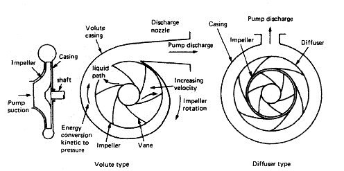
Fig: Centrifugal pumping operation


A vertical, single stage, single entry, centrifugal pump for general marine duties is shown in Figure here. The main frame and casing, together with a motor support bracket, house the pumping element assembly. The pumping element is made up of a top cover, a pump shaft, an impeller, a bearing bush and a sealing arrangement around the shaft. The sealing arrangement may be a packed gland or a mechanical seal and the bearing lubrication system will vary according to the type of seal. Replaceable wear rings are fitted to the impeller and the casing. The motor support bracket has two large apertures to provide access to the pumping element, and a coupling spacer is fitted between the motor and pump shaft to enable the removal of the pumping element without disturbing the motor.

Single entry centrifugal pump

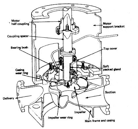
Fig: Single entry centrifugal pump


A vertical multi-stage single-entry centrifugal pump used for deep-well cargo pumping is shown in Figure below. This can be considered as a series of centrifugal pumps arranged to supply one another in series and thus progressively increase the discharge pressure. The pump drive is located outside the tank and can be electric, hydraulic or any appropriate means suitable for the location.

Multi stage centrifugal pump

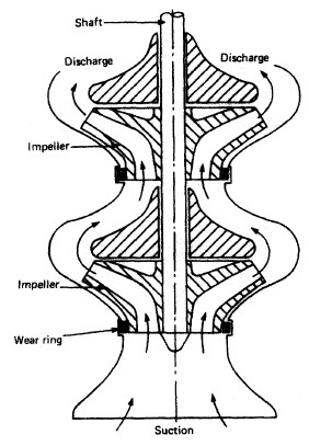
Fig: Multi stage centrifugal pump


A diffuser is fitted to high-pressure centrifugal pumps. This is a ring fixed to the casing, around the impeller, in which there are passages formed by vanes. The passages widen out in the direction of liquid flow and act to convert the kinetic energy of the liquid into pressure energy. Hydraulic balance arrangements are also usual. Some of the high-pressure discharge liquid is directed against a drum or piston arrangement to balance the discharge liquid pressure on the impeller and thus maintain it in an equilibrium position.

Centrifugal pumps, while being suitable for most general marine duties, are not self priming and require some means of removing air from the suction pipeline and filling it with liquid. Where the liquid to be pumped is at a level higher than the pump, opening an air cock near the pump suction will enable the air to be forced out as the pipeline fills up under the action of gravity. If the pump is below sea water level, and sea water priming is permissible in the system, then opening a sea water injection valve and the air cock on the pump will effect priming.

Alternatively an air pumping unit can be provided to individual pumps or as a central priming system connected to several pumps. The water ring or liquid ring primer can be arranged as an individual unit mounted on the pump and driven by it, or as a motor driven unit mounted separately and serving several pumps. The primer consists of an elliptical casing in which a vaned rotor revolves. The rotor may be separate from the hub and provide the air inlet and discharge ports as shown in Figure down. Alternatively another design has the rotor and hub as one piece with ports on the cover. The rotor vanes revolve and force a ring of liquid to take up the elliptical shape of the casing. The water ring, being elliptical, advances and recedes from the central hub, causing a pumping action to occur. The suction piping system is connected to the air inlet ports and the suction line is thus primed by the removal of air. The air removed from the system is discharged to atmosphere. A reservoir of water is provided to replenish the water ring when necessary.

Water-ring primer

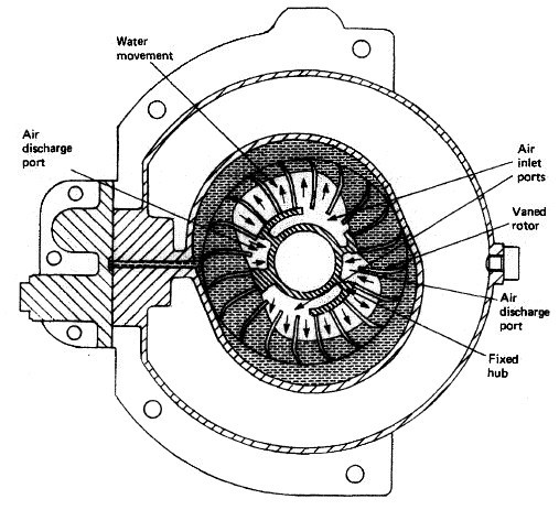
Fig: Water-ring primer


When starting a centrifugal pump the suction valve is opened and the discharge valve left shut: then the motor is started and the priming unit will prime the suction line. Once the pump is primed the delivery valve can be slowly opened and the quantity of liquid can be regulated by opening or closing the delivery valve. When stopping the pump the delivery valve is closed and the motor stopped.

Regular maintenance on the machine will involve attention to lubrication of the shaft bearing and ensuring that the shaft seal or gland is not leaking liquid. Unsatisfactory operation or loss of performance may require minor or major overhauls. Common faults, such as no discharge, may be a result of valves in the system being shut, suction strainers blocked or other faults occurring in the priming system. Air leaks in the suction piping, a choked impeller or too tight a shaft gland can all lead to poor performance.

When dismantling the pump to remove the pumping element any priming pipes or cooling water supply pipes must be disconnected. Modern pumps have a coupling spacer which can be removed to enable the pumping element to be withdrawn without disturbing the motor: the impeller and shaft can then be readily separated for examination. The shaft bearing bush together with the casing and impeller wear rings should be examined for wear.


Section B -- Pump Application Data
B-4A Sealing
The proper selection of a seal is critical to the success of every pump application. For maximum pump reliability, choices must be made between the type of seal and the seal environment. In addition, a sealless pump is an alternative, which would eliminate the need for a dynamic type seal entirely.
Sealing Basics
There are two basic kinds of seals: static and dynamic. Static seals are employed where no movement occurs at the Juncture to be sealed. Gaskets and O-rings are typical static seals.
Dynamic seals are used where surfaces move relative to one another. Dynamic seals are used, for example, where a rotating shaft transmits power through the wall of a tank (Fig. 1), through the casing of a pump (Fig. 2), or through the housing of other rotating equipment such as a filter or screen.


Fig. 1 Cross Section of Tank and Mixer


Fig. 2 Typical Centrifugal Pump
A common application of sealing devices is to seal the rotating shaft of a centrifugal pump. To best understand how such a seal functions a quick review of pump fundamentals is in order.
In a centrifugal pump, the liquid enters the suction of the pump at the center (eye) of the rotating impeller (Figures 3 and 4).


Fig. 3 Centrifugal Pump, Liguid End


Fig. 4 Fluid Flow in Centrifugal Pump
As the impeller vanes rotate, they transmit motion to the incoming product, which then leaves the impeller, collects in the pump casing, and leaves the pump under pressure through the pump discharge.
Discharge pressure will force some product down behind the impeller to the drive shaft, where it attempts to escape along the rotating drive shaft. Pump manufacturers use various design techniques to reduce the pressure of the product trying to escape. Such techniques include: 1) the addition of balance holes through the impeller to permit most of the pressure to escape into the suction side of the impeller, or 2) the addition of back pump-out vanes on the back side of the impeller.
However, as there is no way to eliminate this pressure completely, sealing devices are necessary to limit the escape of the product to the atmosphere. Such sealing devices are typically either compression packing or end-face mechanical seals.


B-4A Stuffing Box Packing
A typical packed stuffing box arrangement is shown in Fig. 5. It consists of: A) Five rings of packing, B) A lantern ring used for the injection of a lubricating and/or flushing liquid, and C) A gland to hold the packing and maintain the desired compression for a proper seal.


Fig. 5 Typical Stuffing Arrangement (description of parts)
The function of packing is to control leakage and not to eliminate it completely. The packing must be lubricated, and a flow from 40 to 60 drops per minute out of the stuffing box must be maintained for proper lubrication.
The method of lubricating the packing depends on the nature of the liquid being pumped as well as on the pressure in the stuffing box. When the pump stuffing box pressure is above atmospheric pressure and the liquid is clean and nonabrasive, the pumped liquid itself will lubricate the packing (Fig. 6).


Fig. 6 Typical Stuffing Arrangement when Stuffing Box Pressure is Above Atmospheric Pressure
When the stuffing box pressure is below atmospheric pressure, a lantern ring is employed and lubrication is injected into the stuffing box (Fig. 7). A bypass line from the pump discharge to the lantern ring connection is normally used providing the pumped liquid is dean.


Fig. 7 Typical Stuffing Box Arrangement when Stuffing Box Pressure is Below Atmospheric Pressure
When pumping slurries or abrasive liquids, it is necessary to inject a dean lubricating liquid from an external source into the lantern ring (Fig. 8). A flow of from .2 to .5 gpm is desirable and a valve and flowmeter should be used for accurate control. The seal water pressure should be from 10 to 15 psi above the stuffing box pressure, and anything above this will only add to packing wear. The lantern ring Is normally located In the center of the stuffing box. However, for extremely thick slurries like paper stock, it is recommended that the lantern ring be located at the stuffing box throat to prevent stock from contaminating the packing.


Fig. 8 Typical Stuffing Box Arrangement when Pumping Slurries
The gland shown in Figures 5 through 8 is a quench type gland. Water, oil, or other fluids can be injected into the gland to remove heat from the shaft, thus limiting heat transfer to the bearing frame. This permits the operating temperature of the pump to be higher than the limits of the bearing and lubricant design. The same quench gland can be used to prevent the escape of a toxic or volatile liquid into the air around the pump. This is called a smothering gland, with an external liquid simply flushing away the undesirable leakage to a sewer or waste receiver.
Today, however, stringent emission standards limit use of packing to non-hazardous water based liquids. This, plus a desire to reduce maintenance costs, has increased preference for mechanical seals.


Mechanical Seals
A mechanical seal is a sealing device which forms a running seal between rotating and stationary parts. They were developed to overcome the disadvantages of compression packing. Leakage can be reduced to a level meeting environmental standards of government regulating agencies and maintenance costs can be lower. Advantages of mechanical seals over conventional packing are as follows:

  1. Zero or limited leakage of product (meet emission regulations.)
  2. Reduced friction and power loss.
  3. Elimination of shaft or sleeve wear.
  4. Reduced maintenance costs.
  5. Ability to seal higher pressures and more corrosive environments.
  6. The wide variety of designs allows use of mechanical seals in almost all pump applications.
The Basic Mechanical Seal
All mechanical seals are constructed of three basic sets of parts as shown in Fig. 9:
  1. A set of primary seal faces: one rotary and one stationary?shown in Fig. 9 as seal ring and insert.
  2. A set of secondary seals known as shaft packings and insert mountings such as 0-rings, wedges and V-rings.
  3. Mechanical seal hardware including gland rings, collars, compression rings, pins, springs and bellows.


Fig. 9 A Simple Mechcanical Seal
How A Mechanical Seal Works
The primary seal is achieved by two very flat, lapped faces which create a difficult leakage path perpendicular to the shaft. Rubbing contact between these two flat mating surfaces minimizes leakage. As in all seals, one face is held stationary in a housing and the other face is fixed to, and rotates with, the shaft. One of the faces is usually a non-galling material such as carbon-graphite. The other is usually a relatively hard material like silicon-carbide. Dissimilar materials are usually used for the stationary insert and the rotating seal ring face in order to prevent adhesion of the two faces. The softer face usually has the smaller mating surface and is commonly called the wear nose.
There are four main sealing points within an end face mechanical seal (Fig. 10). The primary seal is at the seal face, Point A. The leakage path at Point B is blocked by either an 0-ring, a V-ring or a wedge. Leakage paths at Points C and D are blocked by gaskets or 0-rings.


Fig. 10 Sealing Points for Mechanical Seal
The faces in a typical mechanical seal are lubricated with a boundary layer of gas or liquid between the faces. In designing seals for the desired leakage, seal life, and energy consumption, the designer must consider how the faces are to be lubricated and select from a number of modes of seal face lubrication.
To select the best seal design, it's necessary to know as much as possible about the operating conditions and the product to be sealed. Complete information about the product and environment will allow selection of the best seal for the application.

Mechanical Seal Types
Mechanical seals can be classified into several tvpes and arrangements:


PUSHER:
Incorporate secondary seals that move axially along a shaft or sleeve to maintain contact at the seal faces. This feature compensates for seal face wear and wobble due to misalignment. The pusher seals' advantage is that it's inexpensive and commercially available in a wide range of sizes and configurations. Its disadvantage is that ft's prone to secondary seal hang-up and fretting of the shaft or sleeve. Examples are Dura RO and Crane Type 9T.

UNBALANCED:
They are inexpensive, leak less, and are more stable when subjected to vibration, misalignment, and cavitation. The disadvantage is their relative low pressure limit. If the closing force exerted on the seal faces exceeds the pressure limit, the lubricating film between the faces is squeezed out and the highly loaded dry running seal fails. Examples are the Dura RO and Crane 9T.

CONVENTIONAL:
Examples are the Dura RO and Crane Type 1 which require setting and alignment of the seal (single, double, tandem) on the shaft or sleeve of the pump. Although setting a mechanical seal is relatively simple, today's emphasis on reducing maintenance costs has increased preference for cartridge seals.

NON-PUSHER:
The non-pusher or bellows seal does not have to move along the shaft or sleeve to maintain seal face contact, The main advantages are its ability to handle high and low temperature applications, and does not require a secondary seal (not prone to secondary seal hang-up). A disadvantage of this style seal is that its thin bellows cross sections must be upgraded for use in corrosive environments Examples are Dura CBR and Crane 215, and Sealol 680.

BALANCED:
Balancing a mechanical seal involves a simple design change, which reduces the hydraulic forces acting to close the seal faces. Balanced seals have higher-pressure limits, lower seal face loading, and generate less heat. This makes them well suited to handle liquids with poor lubricity and high vapor pressures such as light hydrocarbons. Examples are Dura CBR and PBR and Crane 98T and 215.

CARTRIDGE:
Examples are Dura P-SO and Crane 1100 which have the mechanical seal premounted on a sleeve including the gland and fit directly over the Model 3196 shaft or shaft sleeve (available single, double, tandem). The major benefit, of course is no requirement for the usual seal setting measurements for their installation. Cartridge seals lower maintenance costs and reduce seal setting errors  


Mechanical Seal Arrangements
SINGLE INSIDE:
This is the most common type of mechanical seal. These seals are easily modified to accommodate seal flush plans and can be balanced to withstand high seal environment pressures. Recommended for relatively clear non-corrosive and corrosive liquids with satisfactory' lubricating properties where cost of operation does not exceed that of a double seal. Examples are Dura RO and CBR and Crane 9T and 215. Reference Conventional Seal.

SINGLE OUTSIDE:
If an extremely corrosive liquid has good lubricating properties, an outside seal offers an economical alternative to the expensive metal required for an inside seal to resist corrosion. The disadvantage is that it is exposed outside of the pump which makes it vulnerable to damage from impact and hydraulic pressure works to open the seal faces so they have low pressure limits (balanced or unbalanced).


DOUBLE (DUAL PRESSURIZED):
This arrangement is recommended for liquids that are not compatible with a single mechanical seal (i.e. liquids that are toxic, hazardous [regulated by the EPA], have suspended abrasives, or corrosives which require costly materials). The advantages of the double seal are that it can have five times the life of a single seal in severe environments. Also, the metal inner seal parts are never exposed to the liquid product being pumped, so viscous, abrasive, or thermosetting liquids are easily sealed without a need for expensive metallurgy. In addition, recent testing has shown that double seal life is virtually unaffected by process upset conditions during pump operation. A significant advantage of using a double seal over a single seal. The final decision between choosing a double or single seal comes down to the initial cost to purchase the seal, cost of operation of the seal, and environmental and user plant emission standards for leakage from seals. Examples are Dura double RO and X-200 and Crane double 811T.


DOUBLE GAS BARRIER (PRESSURIZED DUAL GAS):
Very similar to cartridge double seals ... sealing involves an inert gas, like nitrogen, to act as a surface lubricant and coolant in place of a liquid barrier system or external flush required with conventional or cartridge double seals. This concept was developed because many barrier fluids commonly used with double seals can no longer be used due to new emission regulations. The gas barrier seal uses nitrogen or air as a harmless and inexpensive barrier fluid that helps prevent product emissions to the atmosphere and fully complies with emission regulations. The double gas barrier seal should be considered for use on toxic or hazardous liquids that are regulated or in situations where increased reliability is the required on an application. Examples are Dura GB2OO, GF2OO, and Crane 2800.

TANDEM (DUAL UNPRESSURIZED): Due to health, safety, and environmental considerations, tandem seals have been used for products such as vinyl chloride, carbon monoxide, light hydrocarbons, and a wide range of other volatile, toxic, carcinogenic, or hazardous liquids. 


Tandem seals eliminate icing and freezing of light hydrocarbons and other liquids which could fall below the atmospheric freezing point of water in air (32? F or 0? C). {Typical buffer liquids in these applications are ethylene glycol, methanol, and propanol.) A tandem also increases online reliability. If the primary seal fails, the outboard seal can take over and function until maintenance of the equipment can be scheduled. Examples are Dura TMB-73 and tandem PTO. 


Mechanical Seal Selection
The proper selection of a mechanical seal can be made only if the full operating conditions are known:

  1. Liquid
  2. Pressure
  3. Temperature
  4. Characteristics of Liquid
  5. Reliability and Emission Concerns
  1. Liquid: Identification of the exact liquid to be handled is the first step in seal selection. The metal parts must be corrosion resistant, usually steel, bronze, stainless steel, or Hastelloy. The mating faces must also resist corrosion and wear. Carbon, ceramic, silicon carbide or tungsten carbide may be considered. Stationary sealing members of Buna, EPR, Viton and Teflon are common.
  2. Pressure: The proper type of seal, balanced or unbalanced, is based on the pressure on the seal and on the seal size.
  3. Temperature: In part, determines the use of the sealing members. Materials must be selected to handle liquid temperature.
  4. Characteristics of Liquid: Abrasive liquids create excessive wear and short seal life. Double seals or clear liquid flushing from an external source allow the use of mechanical seals on these difficult liquids. On light hydrocarbons balanced seals are often used for longer seal life even though pressures are low.
  5. Reliability and Emission Concerns: The seal type and arrangement selected must meet the desired reliability and emission standards for the pump application. Double seals and double gas barrier seals are becoming the seals of choice.
Seal Environment
The number one cause of pump downtime is failure of the shaft seal. These failures are normally the result of an unfavorable seal environment such as improper heat dissipation (cooling), poor lubrication of seal faces, or seals operating in liquids containing solids, air or vapors. To achieve maximum reliability of a seal application, proper choices of seal housings (standard bore stuffing box, large bore, or large tapered bore seal chamber) and seal environmental controls (CPI and API seal flush plans) must be made. STANDARD BORE STUFFING BOX COVER
Designed thirty years ago specifically for packing. Also accommodates mechanical seals (clamped seat outside seals and conventional double seals.)


CONVENTIONAL LARGE BORE SEAL CHAMBER
Designed specifically for mechanical seals. Large bore provides Increased life of seals through improved lubrication and cooling of faces. Seal environment should be controlled through use of CPI or API flush plans. Often available with internal bypass to provide circulation of liquid to faces without using external flush. Ideal for conventional or cartridge single mechanical seals in conjunction with a flush and throat bushing in bottom of chamber. Also excellent for conventional or cartridge double or tandem seals.

LARGE BORE SEAL CHAMBERS
Introduced in the mid-8o's, enlarged bore seal chambers with increased radial clearance between the mechanical seal and seal chamber wall, provide better circulation of liquid to and from seal faces. Improved lubrication and heat removal (cooling) of seal faces extend seal life and lower maintenance costs.
BigBoreTM Seal Chamber

TaperBoreTM Seal Chamber

Large Tapered Bore Seal Chambers
Provide increased circulation of liquid at seal faces without use of external flush. Offers advantages of lower maintenance costs, elimination of tubing/piping, lower utility costs (associated with seal flushing) and extended seal reliability. The tapered bore seal chamber is commonly available with ANSI chemical pumps. API process pumps use conventional large bore seal chambers. Paper stock pumps use both conventional large bore and large tapered bore seal chambers. Only tapered bore seal chambers with flow modifiers provide expected reliability on services with or without solids, air or vapors.

Conventional Tapered Bore Seal Chamber:
Mechanical Seals Fall When Solids or Vapors Am Present in Liquid
Many users have applied the conventional tapered bore seal chamber to improve seal life on services containing solids or vapors. Seals in this environment failed prematurely due to entrapped solids and vapors. Severe erosion of seal and pump parts, damaged seal faces and dry running were the result.


Modified Tapered Bore Seal Chamber with Axial Ribs:
Good for Services Containing Air, Minimum Solids
This type of seal chamber will provide better seal life when air or vapors are present in the liquid. The axial ribs prevent entrapment of vapors through.improved flow in the chamber. Dry running failures are eliminated. In addition, solids less than 1% are not a problem.
The new flow pattern, however, still places the seal in the path of solids/liquid flow. The consequence on services with significant solids (greater than 1%) is solids packing the seal spring or bellows, solids impingement on seal faces and ultimate seal failure.

Goulds Standard TaperBoreTM PLUS Seal Chamber: The Best Solution for Services Containing Solids and Air or Vapors
To eliminate seal failures on services containing vapors as well as solids, the flow pattern must direct solids away from the mechanical seal, and purge air and vapors. Goulds Standard TaperBoreTM PLUS completely reconfigures the flow in the seal chamber with the result that seal failures due to solids are eliminated. Air and vapors are efficiently removed eliminating dry run failures. Extended seal and pump life with lower maintenance costs are the results.

Goulds TaperBoreTM Plus: How It Works
The unique flow path created by the Vane Particle Elector directs solids away from the mechanical seal, not at the seal as with other tapered bore designs. And the amount of solids entering the bore is minimized. Air and vapors are also efficiently removed. On services with or without solids, air or vapors, Goulds TaperBoreTM PLUS is the effective solution for extended seal and pump life and lower maintenance costs.
  1. Solids/liquid mixture flows toward mechanical seal/seal chamber.
  2. Turbulent zone. Some solids continue to flow toward shaft. Other solids are forced back out by centrifugal force (generated by back pump-out vanes).
  3. Clean liquid continues to move toward mechanical seal faces. Solids, air, vapors flow away from seal.
  4. Low pressure zone create by Vane Particle Ejector. Solids, air, vapor liquid mixture exit seal chamber bore.
  5. Flow in TaperBoreTMPLUS seal chamber assures efficient heat removal (cooling) and lubrication. Seal face heat is dissipated. Seal faces are continuously flushed with clean liquid.

Stuffing Box Cover and Seal Chamber Guide
The selection guide on this page and the Seal Chamber Guide are designed to assist selection of the proper seal housing for a pump application.

JACKETED STUFFING BOX COVER
Designed to maintain proper temperature control (heating or cooling) of seal environment. (Jacketed covers do not help lower seal face temperatures to any significant degree). Good for high temperature services that require use of a conventional double seal or single seal with a flush and API or CPI plan 21.

JACKETED LARGE BORE SEAL CHAMBER
Maintains proper temperature control (heating or cooling) of sea environment with improved lubrication of seal faces. Ideal for controlling temperature for services such as molten sulfur and polymerizing liquids. Excellent for high temperature services that require use of conventional or cartridge single mechanical seals with flush and throat bushing in bottom of seal chamber. Also, great for conventional or cartridge double or tandem seals.
Stuffing Box and Seal Chamber Application Guide
Stuffing Box Cover/Seal Chamber Application
Standard Bore Stuffing Box Cover Use for soft packing. Outside mechanical seals. Double seals. Also, accommodates other mechanical seals.
Jacketed Stuffing Box Cover Same as above but also need to control temperatures of liquid in seal area.
Conventional Large Bore Use for all mechanical seal applications where the seal environment requires use of CPI or API seal flush pans. Cannot be used with outside type mechanical seals.
Jacketed Large Bore Same as Large Bore but also need to control temperature of liquid in seal area.
Tapered Large Bore with Axial Ribs Clean services that require use of single mechanical seals. Can also be used with cartridge double seals. Also, effective on services with light solids up to 1% by weight. Paper stock to 1% by weight.
Tapered Large Bore with Patented Vane Particle Ejector (Alloy Construction) Services with light to moderate solids up to 10% by weight. Paper stock to 5% by weight. Ideal for single mechanical seals. No flush required. Also, accommodates double seals. Cannot be used with outside mechanical seals.

Environmental Controls
Environmental controls are necessary for reliable performance of a mechanical seal on many applications. Goulds Pumps and the seal vendors offer a variety of arrangements to combat these problems.
    1. Corrosion 2. Temperature Control 3. Dirty or incompatible environments
CORROSION
Corrosion can be controlled by selecting seal materials that are not attacked by the pumpage. When this is difficult, external fluid injection of a non-corrosive chemical to lubricate the seal is possible. Single or double seals could be used, depending on if the customer can stand delusion of his product. TEMPERATURE CONTROL
As the seal rotates, the faces are in contact. This generates heat and if this heat is not removed, the temperature in the stuffing box or seal chamber can increase and cause sealing problems. A simple by-pass of product over the seal faces will remove the heat generated by the seal (Fig. 25). For higher temperature services, by-pass of product through a cooler may be required to cool the seal sufficiently (Fig. 26). External cooling fluid injection can also be used.

DIRTY or INCOMPATIBLE ENVIRONMENTS
Mechanical seals do not normally function well on liquids which contain solids or can solidify on contact with the atmosphere. Here, by-pass flush through a filter, a cyclone separator or a strainer are methods of providing a clean fluid to lubricate seal faces. Strainers are effective for particles larger than the openings on a 40 mesh screen. Cyclone separators are effective on solids 10 micron or more in diameter, if they have a specific gravity of 2.7 and the pump develops a differential pressure of 30-40 psi. Filters are available to remove solids 2 microns and larger.
If external flush with clean liquid is available, this is the most fail proof system. Lip seal or restricting bushings are available to control flow of injected fluid to flows as low as 1/8 GPM. Quench type glands are used on fluids which tend to crystallize on exposure to air. Water or steam is put through this gland to wash away any build up. Other systems are available as required by the service.
   

How an oil purifier work?


Bunker oil for combustion on ship's engines is of very low grade. They contain various impurities like particles and water droplets. Large particles in the fuel oil are allowed to settle down in the settling tank before they are pumped into the combustion process piping. After the particles have settled down, the fuel oil will be passed through some sort of filtration using coarse and fine filters.

However, these processes are not sufficient to remove very fine particles and water droplets in the oil.

If you have a bucket of a mixture of dirty oil and water and you leave it in a quiet place to settle, what will happen? You will find that after a long time, the oil will separate out from the water. And if the solid particles are heavy enough, they will also settle at the bottom of the bucket.

Notice that the separation is due to gravity (or specific gravity). Heavy bunker fuel oil has an SG of about 0.95, diesel oil about 0.85 and fresh water has an SG of 1. Because of the difference in Specific Gravity, or SG, the oil will float on top of the water. The solid particles that is heavier than water will sink down. But the above method will take a long time. Furthermore, if the SG's of the mixture are very close, the oil and the water may not be able to separate very well.

An oil purifier uses the same principle for separating dirt or water from oil. Instead of using gravity, it uses centrifugal force.

Through a system of gears, a centrifuge bowl is rotated at high speeds. Oil to be purified is allowed to enter the bowl while it is rotating. The heavier components in the oil are thus forced outwards. The solid particles that are too fine to be removed by filtration are forced towards the circumference of the bowl.

The oil is also heated so as to reduce the SG of the oil. The difference in SG's between the oil and the water will thus be widening. This will enable a better separation between the oil and the water.

Oil purifiers usually maintain a layer of water inside the bowl to act as a seal for the oil. Without the water layer to act as seal, the oil can flow out together with the particles and be lost.

If removal of water is not needed, the centrifuge can be modified so that no water layer is needed. The centrifuge then becomes a clarifier.

Instead of using gravity, the oil purifier makes use of centrifugal force to separate the water from the oil. The solids are removed together with the water.
(Hint: Just turn the picture of the bowl 90 degrees and you will see the similarity between the gravity model and the centrifugal model. )
The actual construction of the purifier will depend on the manufacturer. The most common designs have conical plates to enable the particles to clump together. The larger particles formed will weigh more and are able to be separated from the oil easier.

There will be a ring that acts like a barrier between the oil layer and the water layer. The selection of the size of the ring aperture will depend on the SG of the oil. Wrong selection of the ring will cause either water seal loss or oil loss.

Some purifiers are designed for auto bowl cleaning operation. Some components in the bowl assembly are able to be open by water pressure coming from a separate control system. The bowl cleaning operation is operated at timed intervals. This reduces the need for frequent manual bowl cleaning.

Like all machinery, bearings do wear down, o-rings and seals do become brittle, and bowl contact surfaces do get worn out. The high rotational speeds of the purifier can cause vibrations if the sludge accumulates unevenly. Shear pins or couplings do get broken if there is too high a torque between the bowl shaft and the motor drive.

Monday 10 October 2011

How Does a Centrifuge Work?


Oil is stored in huge quantities on a ship and used for running the engines or lubricating purposes. This oil needs to be cleaned before or during operations. Just find out how it is done with the help of purifiers

Introduction


Oil is the blood of any type of ship and is an important ingredient of the engine room. When I say oil I mean heavy fuel oil, diesel oil and lubricating oil. Each of these oils has their separate systems and need to be cleaned before they are used for various purposes. For example lube oil is used for cylinder lubrication, while diesel oil is used for diesel marine engines. Centrifuge oil cleaning is the best option available on ships to clean large quantities of oil in an economical manner. Of course centrigues have a use in other places apart from ships as well such as offshore & mobile platforms, and on shore industries. In this article we will learn the basics of this cleaning process.

Centrifuge Oil Cleaning

Purifiers are used to clean the oil used on ships and there are heavy oil purifiers, diesel oil purifiers and lubricating oil purifiers. These purifiers come in various sizes and makes, but their general operating principles remain the same as well shall see now. Just take a look at the picture below and see what happens when oil and water (plus other impurities) are supplied to a tank which has the typical structure shown in the picture. In this case the oil will flow from one side, while water will come out at the other side and any solid particles would settle at the bottom.


This method is not very practical but it shows the basic principle of oil-impurities separation. Purifiers and clarifiers work on this principle but make use of the centrifuge force created as a result of fast spinning and you can see this in the next picture. The image shows the construction of a typical purifier which consists of number of perforated discs of inverted bowl shape, stacked one over the other (known as disc stack). Dirty oil enters from top and gets separated into clean oil and dirty component which come out of the respective places as seen in the figure. The centripetal force shown in the picture is created by spinning the entire arrangement along the vertical axis with the help of a powerful motor.


The exact process which is going on between two adjacent discs is shown more clearly in the diagram below which shows the various forces acting on the oil and other impurities which makes the separation possible. Hence it can be noted that reducing the rate of flow will improve quality of purified oil but will make the process slower hence an optimum speed should be used.


How Do Air Purifiers Work?


Change Dirty air to Clean Air
Although they may seem like a new innovation, air purifiers have been around for more than 200 years. What started as protective masks for fireman, air purifiers have now evolved the ability to protect you and your family from airborne pollutants.

As allergies and asthma now affect more than 50 million Americans, the concern for safe indoor air quality has rapidly increased. Now more than ever, Americans are looking for ways to improve their indoor air quality. Air purifiers lead the pack in advancements for cleaner air. AchooAllergy.com represents the top brand air purifier and air cleaner manufacturers including Austin Air, Blueair, IQAir, and AllerAir.

Allergens like smoke, mold spores, pollen, bacteria, viruses, pet dander, and other pollutants damage your lungs and immune system. Unfortunately, most of these irritants cannot be seen by the naked eye. Air purifiers filter allergens and pollutants seen or unseen by the human eye. To remove these objects, air purifiers typically use filters, electrical attraction, or ozone.

Air filters utilize fine sieves that filter particles from circulating air. As air flows into the air purifier, the finer the sieve used, the smaller the particles it traps. The accepted benchmark for air filters has been set by the High Efficiency Particulate Air (HEPA) filters, which are guaranteed to trap 99.97% of airborne particles larger than 0.3 microns. Microns are the standard unit used for measuring air particles. Each micron is equivalent to 1/25,400 of an inch. The naked eye cannot see anything smaller than 10 microns, so pollutants like bacteria and viruses escape detection. Room air conditioner filters only capture particles 10.0 microns or larger. HEPA filters remove smaller allergens like dust, smoke, chemicals, asbestos, pollen, and pet dander.

The more times the air passes through the HEPA filter, the cleaner the air becomes. The room capacity of a HEPA air purifier will determine whether the air cleaner can handle your air purifying needs. Top-of-the-line brands like Austin Air air purifiers will provide approximately 6 air exchanges per hour in an average room and contain an average of 15 lbs of activated carbon/zeolite blends, which adsorb chemicals and odors.

In addition to the HEPA filter, brands like AllerAir air purifiers and IQAir air purifiers offer an optional medical grade ultra-violet (UV) light system, used to quickly kill viruses, bacteria, and fungi upon entry into the air purifier. UV light also protects the HEPA filter from biological and viral contamination.

Electrical attraction is another technology utilized by air purifiers to trap particles. Three types of air cleaners work using electrical attraction: electrostatic precipitating cleaners, electret filters, and negative ion generators.

Electrostatic precipitating cleaners or “electronic” air purifiers draw particles in by fan and charge them with a series of high-voltage wires. Several plates (precipitating cells) carry the opposite electrical charge and attract the contaminants as they pass by the plates. Electronic air purifiers are perfect for individuals who don’t want to worry about the costly replacements of HEPA filters. The downside to these units is that many create a nasty byproduct, ozone.

Electret filters in air purifiers use synthetic fibers that create static charges to attract particles. Electret filters are offered in a variety of types including plain, pleated, disposable or reusable. Depending on the type of filter you need, will determine how often the filter requires replacement.

Some brands like the Blueair air purifier combine the HEPA technology with their own electrostatic media filter technology, which charges the incoming particles instead of the filter. By marrying the two unique purification systems together, Blueair created a more effective air cleaner.

Negative ion generators or ionic air purifiers use tiny, charged wires or needles to create gas molecules with negative charges or ions that adhere to the airborne particles and collect in the filter. However, many ions end up back in the air, sticking to furnishings and other surfaces that may be stained by them.

Ionic air purifiers only remove certain types of particles and aren’t always effective against gases, chemicals, or odors. Some ionic air purifiers have been shown to re-circulate the same dirty particles that they draw in, making them much less effective than traditional air purifiers using HEPA filtration.

Instead of using filters to trap particles, ozone generators use high voltage electrical currents to convert oxygen to ozone, which acts as a powerful oxidant and breaks down molecules and microorganisms in the air. Several tests have proved that ozone generators are not very effective at removing indoor allergens.

Ozone, in fact, can be hazardous to your health, and both ozone generators and ionic air cleaners emit ozone. In nature, lightning creates ozone when it cuts through oxygen molecules in the air. In the atmosphere, ozone helps protect us from harmful UV rays; however, on the ground level, ozone is a powerful lung irritant. When created artificially, ozone can actually aggravate allergies and asthma, damaging the lining of nasal passages and lungs, causing coughing, throat irritation, chest pain, and shortness of breath. The Environmental Protection Agency and the American Lung Association advise against using ozone generators, which is why AchooAllergy.com does not carry them.

Asbestos and radon are growing problems in homes today. Heating devices produce carbon monoxide and other dangerous gases, and chemicals like formaldehyde and ammonia are increasing in your home environment. Since most Americans stay indoors an average of 90% of the time, providing fresher and cleaner air has never been more important.

Finding an environment-friendly solution has become much easier. Learn about air purification today. The right air purifier will provide asthma and allergy sufferers with air free from airborne pollutants and establish healthy indoor air quality for you and your entire family.

How is Power Generated and Supplied on a Ship?


A ship is like a floating city with all the privileges enjoyed by any normal land city. Just like a conventional city, the ship also requires all the basic amenities to sustain life on board; the chief among them is power or electricity. In this article we will learn as to how power is generated and supplied on board a ship.

Power generation On board

Shipboard power is generated using a prime mover and an alternator working together. For this an alternating current generator is used on board. The generator works on the principle that when a magnetic field around a conductor varies, a current is induced in the conductor.
Wartsila Sets How is Power Generated and Supplied on a Ship?
The generator consists of a stationary set of conductors wound in coils on an iron core. This is known as the stator. A rotating magnet called the rotor turns inside this stator producing magnetic field. This field cuts across the conductor, generating an induced EMF or electro-magnetic force as the mechanical input causes the rotor to turn.
The magnetic field is generated by induction (in a brushless alternator) and by a rotor winding energized by DC current through slip rings and brushes. Few points to be noted about power on board are :
  • AC, 3 phase power is preferred over DC as it gives more power for the  same size.
  • 3 phases is preferred over single phase as it draws more power and in the event of failure of one phase, other 2 can still work.
Power Distribution on board
msb 300x184 How is Power Generated and Supplied on a Ship?
The Power Distributed on board a ship needs to be supplied efficiently throughout the ship. For this the power distribution system of the ship is used.
A shipboard distribution system consists of different component for distribution and safe operation of the system. They are:
  • Ship Generator consisting of prime mover and alternator
    Main switch board which is a metal enclosure taking power from the diesel generator and supplying it to different machinery.
  • Bus Bars which acts as a carrier and allow transfer of load from one point to another. Circuit breakers which act as a switch and in unsafe condition can be tripped to avoid breakdown and accidents. Fuses as safety device for machinery.
  • Transformers to step up or step down the voltage. When supply is to be given to the lighting system a step down transformer is used in the distribution system.
  • In a power distribution system, the voltage at which the system works is usually 440v.
  • There are some large installations where the voltage is as high as 6600v.
  • Power is supplied through circuit breakers to large auxiliary machinery at high voltage.
  • For smaller supply fuse and miniature circuit breakers are used.
  • The distribution system is three wires and can be neutrally insulated or earthed.
  • Insulated system is more preferred as compare to earthed system because during an earth fault essential machinery such as steering gear can be lost.
Emergency Power
gene emer 300x198 How is Power Generated and Supplied on a Ship?
In case of the failure of the main power generation system on the ship, an emergency power system or a standby system is also present. The emergency power supply ensures that the essential machinery and system continues to operate the ship.
Emergency power can be supplied by batteries or an emergency generator or even both systems can be used.
Rating of the emergency power supply should be made in such a way that it provides supply to the essential systems of the ship such as
a)     Steering gear system
b)    Emergency bilge and fire p/p
c)     Watertight doors.
d)    Fire fighting system.
e)     Ships navigation lights and emergency lights.
f)      Communication and alarm system.
Emergency generator is normally located outside the machinery space of the ship. This is done mainly to avoid those emergency situations wherein access to the engine room is not possible. A switch board in the emergency generator room supplies power to different essential machinery.